
Weir Valves & Controls USA Inc. Ipswich, MA
For my second co-op I worked as a member of the nuclear engineering department at Weir Valves. Working at Weir allowed me to learn a lot about 3D modeling in SolidWorks. I also was involved in the diagnostic testing of valves, FEA analyses, and CFD analyses.
Poppet Redesign Project
I spent most of my time at Weir working on a project that aimed to improve their already existing poppet designs by increasing manufacturing efficiency, repeatability, design consistency, and first time yield. Each different nuclear power plant that Weir sells poppets to has a different poppet design. In production, from start to finish, each poppet required 5 engineering prints to manufacture. With about 20 different poppet designs and 5 prints for each poppet, another engineer and I created 20 new 3D models in SolidWorks and 100 corresponding technical prints.

Final machine print for poppet. Dimensions and geometric tolerances hidden per request of Weir.

Cross-sectional view of final machine poppet model.
|

Final machine model of poppet
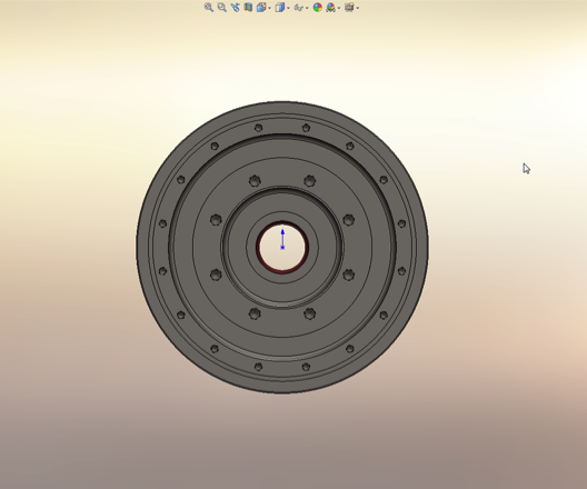
Side view of final machine poppet model depicting bolt circles.
|
Computer Analyses
Finite Element Analysis
At Weir I ran a few FEA analyses to see how certain valve bodies would preform under loading conditions specified by customers. Below is one example of an analysis I ran in order to see how the sealing surfaces of this valve body would deform.

FEA simulation of valve body.

Displacements of nodes on sealing ring surface of valve body in the x, y, and z directions.
From running the above FEA analysis according to the loads and moments specified by the customer it was determined that the valve would deform too much and would most likely leak under the specified loading conditions. It can be seen in the data that the x and y displacements around the seat ring would have been larger in magnitude than the z displacement, but that the z displacement varied more around the seat ring. The deformations shown were all under 0.002", but were determined to be too large for proper performance of this valve.
Computational Fluid Dynamics
For one customer we needed to run CFD analyses to show the resulting pressure drops from different valve designs in order for the customer to select the most optimal valve for their design requirements.

Screenshot from CFD analysis.
Valve option 1.

Valve option 3.
|

Valve option 2.
|

After running multiple analyses, the results showed that valve option 2 and 3 resulted in the smallest pressure drops and those valves were recommended to the customer.
Diagnostic Testing of Valves
At Weir I was very involved in the diagnostic testing of air and motor operated valves in order to approve valves for shipments to different nuclear plants around the world. The goal of the diagnostic testing preformed by the engineering department was to make sure that the seating torque of the valves was of an appropriate magnitude, the rotation of the valve was between 85 and 90 degrees and that the electronic signals within the valve were behaving as expected.

Example of diagnostic data gathered through the combination of QUIKLOOK software, Teledyne strain gauge, and rotary position sensor.

Teledyne strain gauge used to test torque supplied by valve shaft.
|

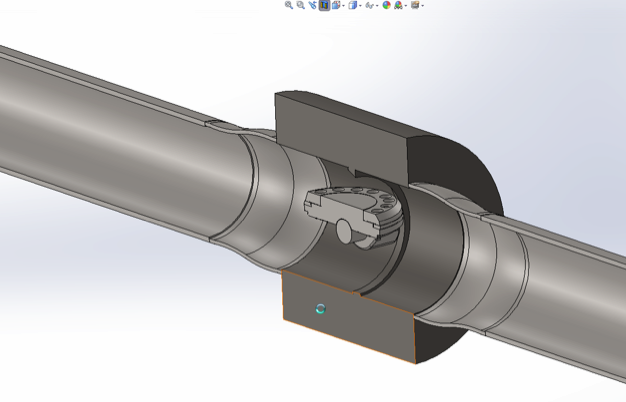
Air Operated Valve mounted in test stand for diagnostic testing.
|
